Centrifuge

Its is a process in which components are separate on basis of size ,shape, length, density ( in other words its is a separation process of material).its is a machine which is use in science laboratory such as biotechnology lab.

in this apparatus DNA ,RNA, amino acids and protein are separated by plant or animals cell or tissue (bacterial genetic material also be separated).

Principal:

Its works on density of components desire to separate in form of homogeneous solution

F=Mw²r

F=intensity of centrifugal force

M= Mass of particle

w= angular volecity of rotation

r=distance of migrating particle from center of axis of rotation

Types of Centrifuge:

1.small bench top centrifuge:

a).in this centrifuge without chill solution can be separated.

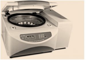
b).blood ,serum .etc are separated

c).slow in speed upto 4000 rpm

d).100 eppnodroff tube are can be  loaded in a time.


2.Micro Centrifuge:

a).2mm volume of eppnodroff tube

b).10,000 eppnodroff tube can be loaded

c).protein are separated

3.High speed centrifuge:

a).50,000 eppnodroff tube are loaded

b).sub.organelles are separated

c).17000 rpm speed

4.ultra high speed centrifuge:

a).90,000 eppnodroff tube are loaded.


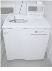
b).chilled material are used

c).microorganisms are separated

  • Rotar in centrifuge
  • Fixed rotar

horizontal solution are in rotation and clearly pellets are separated debris are obtain

  • swimming bucket rotar

its solution in vertical position in rotation and no clearly pellets are separated

Power Amps:

Power Amplifier is electronics circuit which amplify the signal. In other words amplifier is circuit or electronic device which make week signal strong. Amplifier is an essential part of mostly used devices like, mobile , Television, Audio amplifier, CD players, tape recorders etc. In other words amplifier is important part of any system, transmission system or any other. The main        part of the amplifier is transistor an electronics  component which amplify the signal. any signal which is amplified in micro volt or amps and output is in few amps. It is said that amplifiers can amplify signal up to 1000s of times, it is true. but keep in mind it cannot be 1 volt to 1000 volt but it can be from 1u volt to 1 volt which is million times amplified.

How Amplifier works:

The working of amplifier is as we week signal is applied on the base of the transistor it makes changes in current or voltage flowing from emitter to collector of transistor. Thus voltage measure on the resistor which is connected at collector in series, is high. it is called that signal applied on base of transistor is amplified. The value of resistor in series with collector is always high rather than resistance of emitter. These resistances actually cause amplification of signal. look at figure:

Ampere

Ampere is international  unit for current. The flow of charges is called current. if one coulomb charge flow in one second then it is called one ampere of current. ampere is not coulomb but coulomb per second. it is denoted by A or amp. in consumption  Ampere is  as: A=V/I   this is called ohm’s law. this will be discussed in next article.The batteries are rated in AH Ampere- Hours. This means how much current a battery can provide for one hour. this is ideal condition.

Ampacity

The term ampacity comes from ampere  capacity. this means capacity of amperes of a wire which it can carry. Proper definition we can make is the ability of any wire to carry out the current in amperes is called ampacity of that wire.The ampacity of wires changes with size and voltage and also material of wires. Copper wires have more ampacity than aluminum or any other metal.

Some details are as below:

Wire Size (AWG)    Copper conductor (A)                  Aluminum Conductor (A)

14                                       20                                                             ….

12                                       25                                                             20

10                                       35                                                             30

8                                         50                                                             40

6                                        65                                                             50

4                                         85                                                             65

2                                         115                                                           90

1                                        130                                                            100

1/0                                     150                                                            120

2/0                                     175                                                            135

3/0                                     200                                                            155

4/0                                     230                                                            180

If you have any suggestions please comment…..

Ammeter

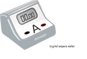
Ammeter or Ampere meter is instrument which measures quantity of current in closed loop. in other words ammeter is device which measures the current of load or line. The ammeter now a days comes in multi meter as a option. The old multi meter or ammeter was analog which told the quantity of current by moving a needle to respective value of current. Now a days it is era of digital world so multi meter or ammeter also are available in digital which show value in figures. these kind of meters are very accurate rather than analog meters.

Working of Ammeter:

The analog meter had scales rated over the different values and a needle indicated the  value by moving over the scale according to value of current. there are two resistances in parallel of a ratio difference. when current passed throw the resistance and then from coil of needle to move it which moves over scale to indicate the value. In modern era digital meter show value in figures. these meter covert analog signal in digital form by ADC “Analog to Digital Converters”. and then scan over LCD or 7 segment display.

Alternator

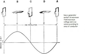
Science is not a magic. it always exists in nature and scientists or engineer only make them usable or visible by machines. same like this electricity is not magic, it is also produce one of the nature quality which states” when a conductor is moved in magnetic field , there is potential difference on conductor  end” this phenomena is used in alternator or AC generator. when a conductor “armature” is rotated in magnetic field it produces potential difference of voltage which cause to move charges from one end to other of closed loop. these moving charges are called current.


Alternator is second name of electrical generator. it produces the alternating voltage and current.  These generators are rated in mostly KVA. it consists of two major parts, engine and generator. The engine rotates the shaft of alternator and alternator produces the electricity which is collected on its terminals. The alternators are of 2 basic types. Single phase and Three Phase alternators. Single phase alternators produce single phase electricity and three phase produce three phase electricity

Generator Synchronization

The Generator is electrical generator which produce AC or dc power. The synchronization phenomena is mostly considered for the ac power generators or alternators.  Synchronization is to match the frequency, voltage and phase angle of the two or more working generators and for three phase, phase sequence. In practical mostly used and simplest method is lamp testing. In this method one lamp or bulb is inserted between two alternators phases. the lamp must be between the Generator and line phases RYB simultaneously. When the bulb is on, it means generators are not synchronized and you have to change the speed of alternator for synchronization. if bulb is off then your alternator is synchronized.

The other method is  sync meter which do the same work by digitally or analog measuring the voltage and frequency of both alternators or alternator and line.


The things always keep in mind for the synchronization are:


RMS voltage,

Frequency,

Phase angle,

and phase sequence.


These all things are matched when your frequency is matched if both of the alternators are, of same capacity or rating.

The rating is different then there may be difficulty in synchronization but can be synchronized. The synchronization of Alternators are always done by change the speed or Alternators for same design frequency and voltage. Synchronization is mostly done on power plants for adding the new upcoming generator in line.

Alternating current

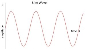
Alternating current or AC current is which changes its magnitude and direction at every moment. AC current may have different shapes as like sinusoidal, saw tooth, square wave etc. Mostly used in power system is sinusoidal for AC current and voltage. AC current is produced by generators or Alternators. AC current used in power system is in mostly 50hz or 60 hz.

Actuator

Actuator is a arm, coil, or something like this which converts one energy to mechanical energy for releasing or closing gas or liquid. in other words we can say it is a type of special motor.  The actuator can be electrical biased, mechanical biased, thermo biased, hydraulic biased or pneumatic biased.

Electrical Biased Actuator: electrical biased actuators are solenoids which are used to control flow, it can be fluid or pneumatic flow. solenoid also control electrical energy.

Mechanical Biased Actuator: Mechanical biased actuators are hydraulic or pneumatic cylinders which control the flow of fluid or compressed air.

Thermo Biased Actuator: Actuators which are actuated by thermally or magnetically are called thermo biased actuators. 

AC adapter

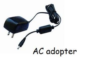
AC adopters are basically rectifiers which convert AC power to DC power on different voltage and current levels. Actually ac adopters are external power supplies with AC plug in. these adopters can be of different voltage levels of input as 110v ,220v.230v etc. The power of these adopter may vary from mille watt  to mega watts. Adopter may have out pins or as USB plugs. with different companies it has different style and shape. AC adopter may have output voltage 3v,6v,9v,12v,19v,24v etc according to requirement with different current ranges. The current ranges vary from mille amps to kilo amps. For working of Ac adopter refer to the Rectifiers.

WP2Social Auto Publish Powered By : XYZScripts.com