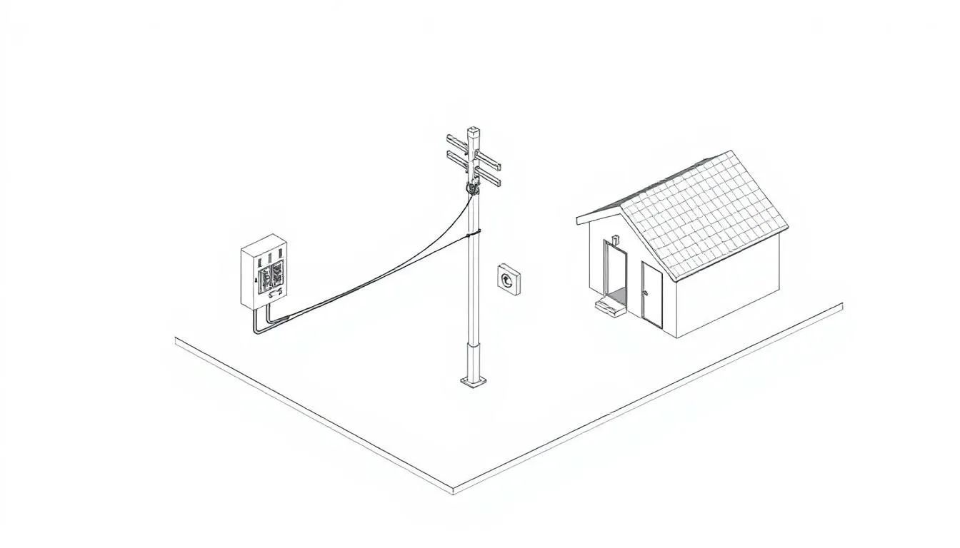
One Line Diagram Electrical
Symbolism in One Line Diagram Electrical Understanding Schematic Representation Old electrical drawings can look like a spider web. Full schematics

Symbolism in One Line Diagram Electrical Understanding Schematic Representation Old electrical drawings can look like a spider web. Full schematics
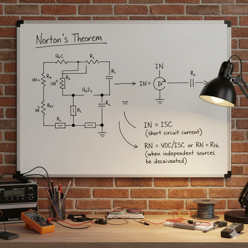
Norton’s theorem it is a fundamental concept in electrical circuit analysis that allows for the simplification of complex linear circuits.
Negative resistance is a unique and counterintuitive concept in electronics that has captivated researchers and engineers for decades. This phenomenon

Motion control forms the base for many automated tasks. It helps machines follow set paths with little error. Let’s start

Invention of the Microphone Microphone: Back in the late 1800s, folks like Emile Berliner and Thomas Edison pushed early mic
What Is a Microcontroller? A microcontroller acts like the brain in small electronic systems. It processes data and controls actions

What are Ferrite memory Cores? Ferrite core memory cores are small, ring-shaped rings. They are constructed from a unique ceramic
What is a Magnetic Core? A magnetic core is a special material that helps focus and strengthen magnetic fields. Think

What is a Laser Diode? Laser diodes make light using a clever trick of physics. It all starts with a
Kirchhoff’s Circuit Laws: Kirchhoff’s Circuit Laws of Electrical circuits can seem like tangled puzzles. Imagine a network with many wires,
What Are Integrated Circuits? The Building Blocks: Transistors and Semiconductors Integrated circuits are small powerhouses. They hold many tiny parts
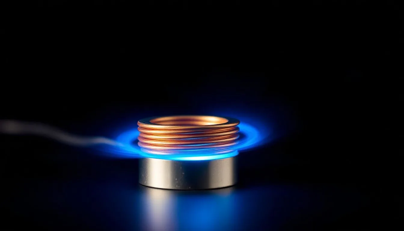
Principles of Induction Heating Getting to grips with induction heating means understanding its basic science. This powerful method uses electricity
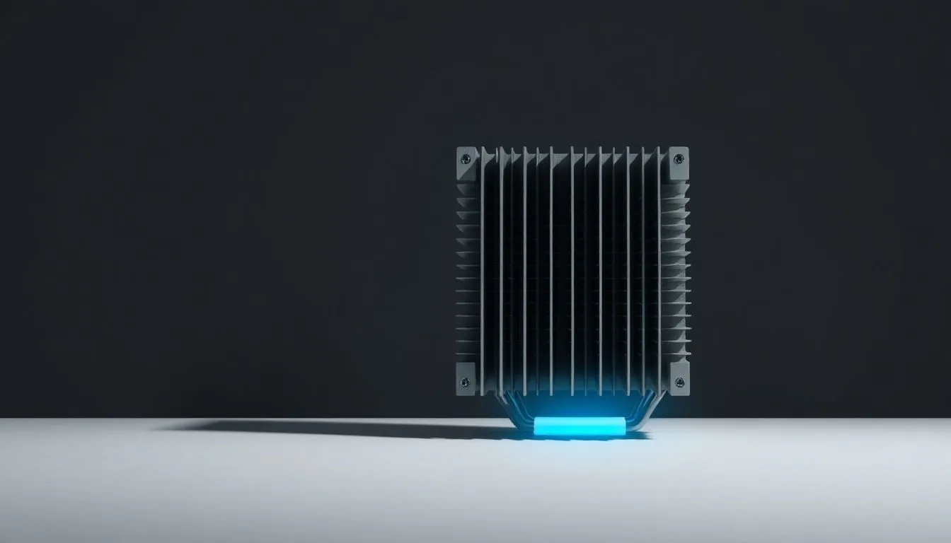
What is Heatsink From the smartphone in your pocket to massive supercomputers, heat is a constant challenge. Every electronic device
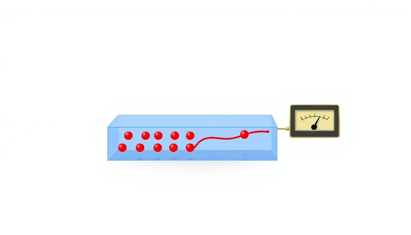
What is the Hall Effect? The Hall effect and hall effect sensors ,happens when an electric current flows through a

Mathematical Formulation of Gauss’s Law Gauss’s Law takes these ideas and puts them into a neat math rule. This rule
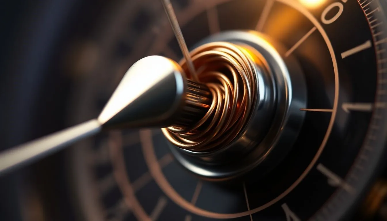
Principles of a Galvanometer A galvanometer works because of a basic rule: electricity and magnetism interact. Using this idea, these

What is Frequency Modulation? Frequency Modulation, or FM, is a way to send information using a high-frequency radio wave. Think
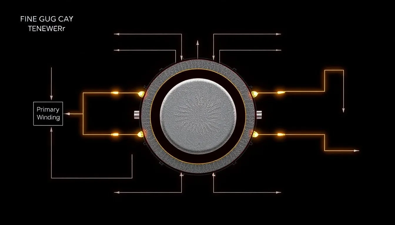
Principles of Fly back Transformers How a Fly back Transformer Works: A fly back transformer operates on a unique principle
What is Magnetic Flux? Magnetic flux or flux linkage is simply a measure of the total magnetic field passing through

How Fluorescent Lamps Work: This section explains how fluorescent lamps make light. We will explore the scientific steps that produce
Field Effect Transistor: The Field Effect Transistor, or FET, stands as a core piece of modern electronics. It is a
Unveiling Faraday’s Law: Imagine a world without electric lights. Think about life without motors, or even the small devices that
Fundamentals of Energy Management What is Energy Management? Defination Energy management is a planned way to watch, control, and cut

Understanding Enameled Wire What is Enameled Wire? Enameled wire has a core made of metal, usually copper or aluminum. This
Embedded System’s Formation Hardware Architecture The physical parts of an embedded system are built for a specific purpose. They are
Foundations of Electronic Engineering: This section lays the basic rules. It explains the science and building blocks electronic engineers use
What is an Engine control computer or (ECM)? Defining the Automotive Brain An Engine control computer or (ECM) is your
What Are Electronic Components? Electronic components are the fundamental pieces of any electronic circuit. They are small devices, both passive

How Electron Microscopes Work Electron microscopes use a focused beam of electrons instead of light to create an image. First,
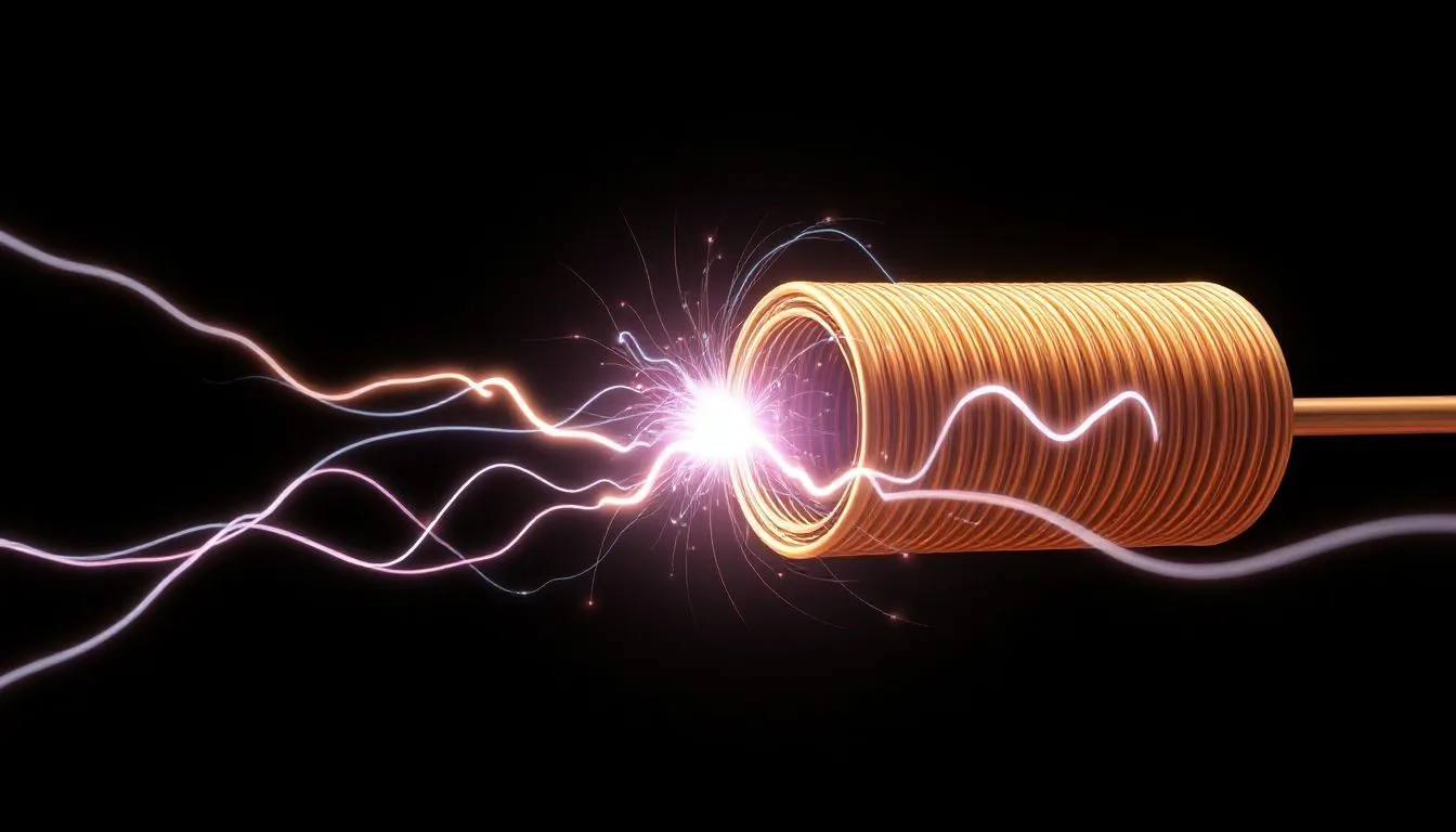
How Electromagnet Works, Applications, and Innovations Introduction: An electromagnet is a special kind of magnet. It gets its magnetic power
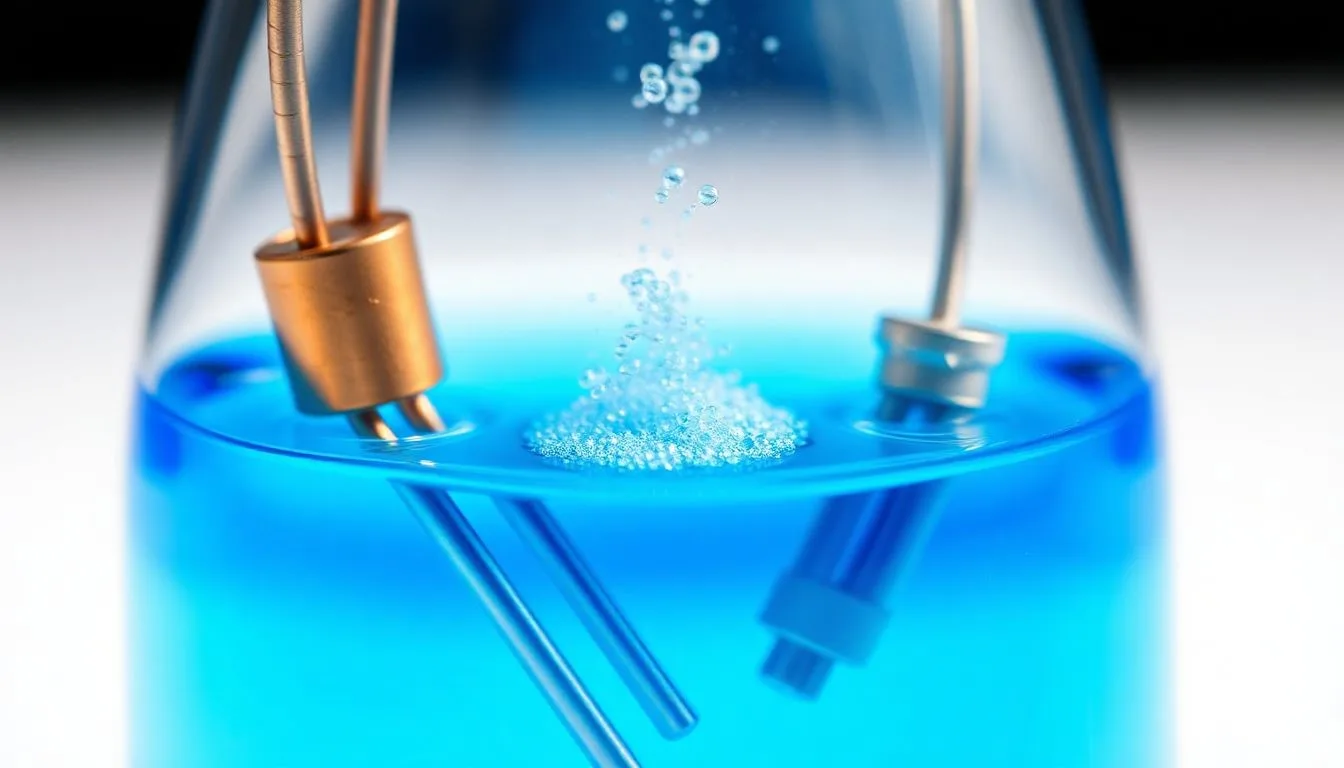
What is Electrolysis? Electrolysis is a chemical process. It uses electrical energy to drive non-spontaneous chemical reactions. This means reactions

What are Electrodes? Have you ever wondered what makes electricity flow in a device? Electrodes are often the answer. They

Fundamental Electrical Quantities Electrical Measurements section sets the stage by defining the main electrical parameters you often measure. It’s vital

Principles of Electrical Machines The Electromechanical Conversion Process Electrical machines work by turning one type of energy into another. They

What is Electrical Load? Electrical load describes the total power used by all devices connected to a power source. Think

What is Electrical Insulation? Definition and Core Principles Electrical insulation is a material that strongly resists electric current. It does
Electrical Impedance Definition Have you ever wondered why some circuits act differently with AC current? Electrical impedance holds the answer.

What is an Electrical Conductor? Definition and Core Principles An electrical conductor is a material. It lets electric current pass

Science is not a magic. its all About research and development for the well being of mankind.