How to Calculate Transformer Core Loss and Equivalent-Circuit Values
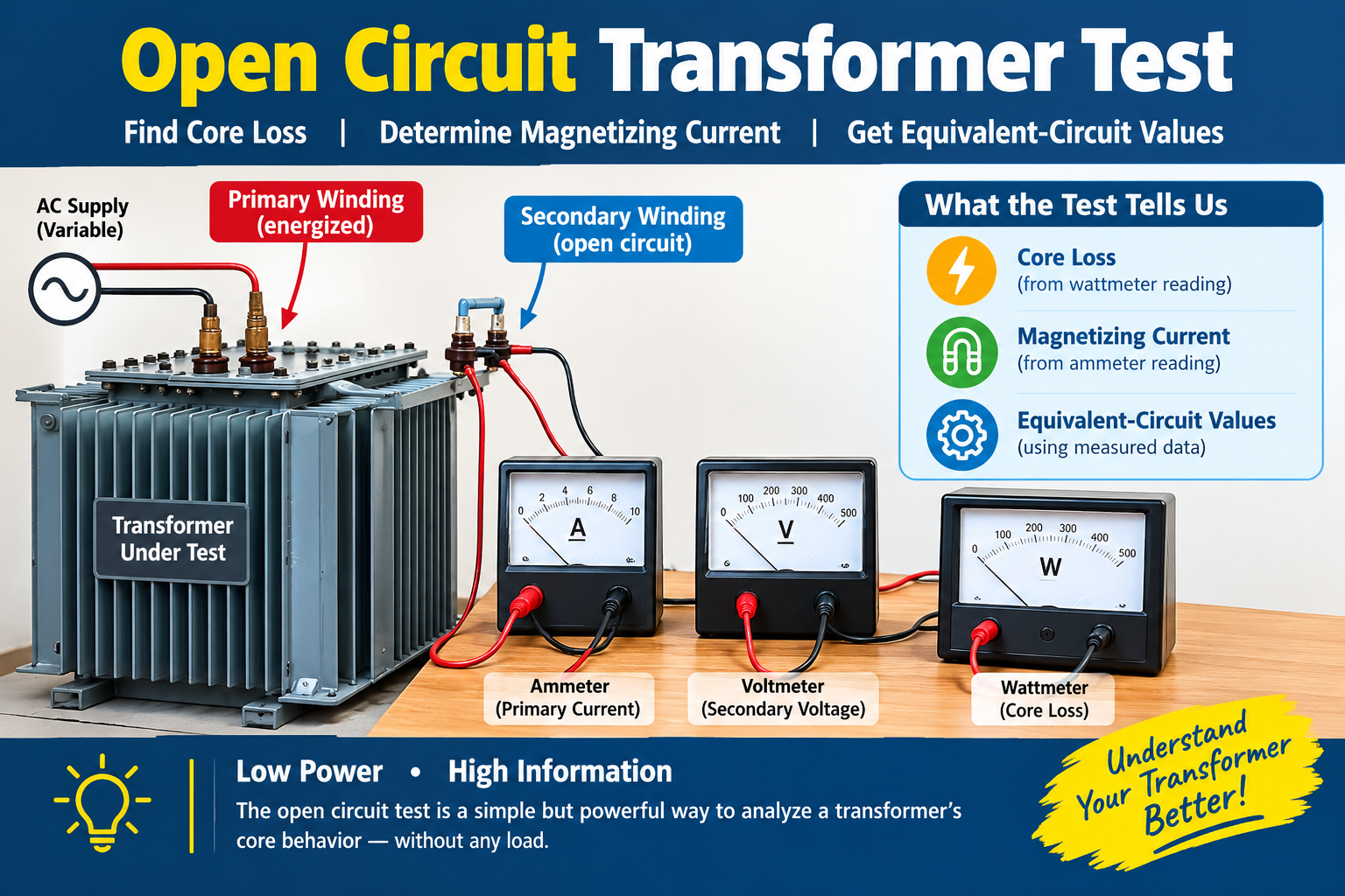
A transformer does not need to be connected to a load for us to learn a great deal about its performance. With an open circuit test, we can estimate its core loss, examine its magnetizing current, and calculate key values for the transformers equivalent circuit all without running it at full load.
The test is commonly used on single-phase transformers. During the test, we measure the applied voltage, no-load current, input power, and voltage induced in the open winding. From these readings, we can estimate core loss, the turns ratio, no-load power factor, and the shunt resistance and reactance used in the equivalent-circuit model.
No-load tests are also performed on motors and generators, but the setup and calculations are different. This article focuses on the transformer test.
What Does a Transformer Open Circuit Test Measure?
How the no-load test works
In an open circuit test, AC voltage at the transformer rated frequency is applied to one winding while the other winding is left disconnected from any load. Because the open winding has no load connected, its current is effectively zero.
The energized winding still draws a small current. This is the no-load current. it establishes magnetic flux in the core and supplies the energy lost through hysteresis and eddy currents. Since the secondary current is negligible, winding copper loss is small compared with core loss.
The test is widely used to determine the shunt-branch values in a transformer equivalent circuit. These values help engineers estimate efficiency and voltage regulation when combined with results from a short-circuit test.
Measure and record these quantities in open circuit test:
Applied voltage,(V) the RMS voltage across the energized winding.
No-load current, (I):the current drawn by that winding.
Input power, (P): the wattmeter reading.
Open-circuit test secondary voltage: the voltage induced across the unloaded winding.
The measured voltage ratio provides an estimate of the turns ratio:
At no load, the wattmeter reading is treated mainly as core (iron) loss. A small amount of copper loss remains because the energized winding still carries no-load current.
Why rated voltage and frequency matter
Core flux depends on both voltage and frequency. If the applied voltage is increased while frequency stays constant, the core flux also increases. Near saturation, the current can rise sharply, causing extra heating and unreliable readings.
For a meaningful result, perform the test at the transformers rated voltage and frequency. Never exceed the nameplate voltage or use an unsuitable supply frequency.
Choose which winding to energize
In many laboratory setups, the low-voltage winding is energized and the high-voltage winding is left open. This allows the test to be carried out with a lower supply voltage. However, the correct arrangement depends on the transformer and the test procedure, so always check the nameplate and laboratory instructions.
A typical circuit uses a variable AC source (variac), a fuse or circuit breaker, an ammeter, and the wattmeter, current coil in series with the energized winding. Connect the voltmeter and the wattmeter across that winding. A second voltmeter can measure the induced voltage across the open winding.
Simplified connection guide
– AC source > variac > protective fuse > ammeter > wattmeter current coil > energized winding
– Voltmeter and wattmeter connected across the energized winding
– Open winding: left unconnected to a load
– Secondary voltmeter: connected across the open winding’s terminals
Instruments and pre-open circuit test checks
Before switching on:
1. Inspect the transformer, leads, insulation, and terminals.
2. Confirm that the winding terminals are identified correctly and the equipment is properly earthed.
3. Check instrument connections and polarity, and make sure all connections are secure.
4. Keep the secondary open, guard exposed live parts, and set the variac to zero.
Open Circuit Test Procedure
Connect and energize the transformer
Connect the voltmeter across the energized winding. Wire the ammeter and wattmeter current coil in series with it, then connect the wattmeter potential coil across the supply terminals. Leave the other winding open and verify the connections before applying power.
Switch on the supply with the variac at zero. Increase the voltage slowly until it reaches the winding’s rated value. Watch the current and listen for unusual noise as the voltage rises. An unexpected current surge or abnormal sound is a reason to stop and check the setup.
Take readings and shut down
Once the readings are stable, record (V), (I), (P), and the open circuit test on secondary voltage. If you need to study how the transformer behaves at different voltages, take additional readings below the rated value. Do not exceed the nameplate voltage.
When the test is complete, turn the variac back to zero before switching off the supply. Isolate the equipment before changing any connections. The open winding can still develop its rated induced voltage, so do not assume that an unconnected terminal is safe to touch.
Calculate Core Loss and Equivalent-Circuit Values
Calculate the no-load power factor
Use the voltage, current, and wattmeter readings to find the no-load power factor:
cos\=\frac{P_0}{V_0 I_0}
\]
Here, (P) is input power in watts, (V) is the applied RMS voltage, and (I) is the no-load RMS current. The no-load power factor is usually low because much of the current is reactive and is needed to establish the core flux.
Separate the current components
The no-load current can be resolved into a working component and a magnetizing component:
The working component, (I_w\), accounts for the power associated mainly with core loss. The magnetizing component, \(I_m\), establishes the magnetic flux. These are calculated equivalent-circuit components; they are not separate currents that must be measured with additional ammeters.
The resistance (R) represents the core-loss effects, including hysteresis and eddy-current losses. The reactance (X) represents the core’s magnetizing behavior.
These are approximate equivalent-circuit values, and they depend on the model and the winding side to which they are referred. If you need to transfer an impedance value to the other winding, use the square of the turns ratio.
How to Interpret the Results of open circuit test
What the readings tell you
During the open circuit test the wattmeter reading is treated mainly as core loss. Hysteresis and eddy-current losses are the main contributors, but this test does not separate them individually. A small amount of copper loss remains in the energized winding.
The no-load current should be much lower than the transformer’s rated load current. Core loss varies with voltage and frequency, and the current can rise rapidly as the core approaches saturation. Compare your results with the transformer’s nameplate, manufacturer’s data, or measurements from a known-good unit rather than relying on a single universal pass/fail value.
Common causes of inaccurate readings
Incorrect open circuit test, wattmeter polarity, unsuitable instrument ranges, loose terminals, a supply frequency that does not match the rating, and instrument burden can all affect the result. Make sure the secondary is truly open and check the calibration and connections if the readings appear unusual. further reading about electric power distribution.